

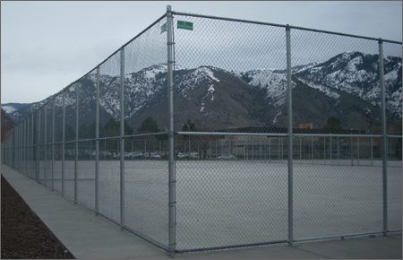
Hot Dipped Galv. Chainlink Fence is applied in fabrication of Perimeter Security Fencing System. The construction of chain wire fencing system for high security application include not only mesh panels, also gates and barbed wire concertina. Galvanized chain wire fence is used as barrier for playing ground, construction sites, railways, expressways, airport, residences and various borders.
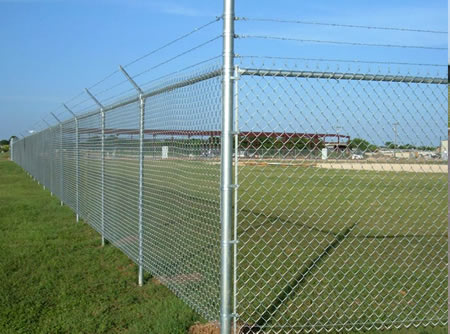
Framework Chainlink Panels
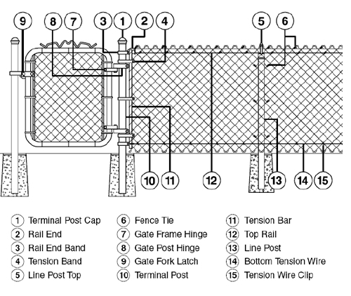
Fence Post: An upright tubular or fabricated steel member for supporting fencing material.
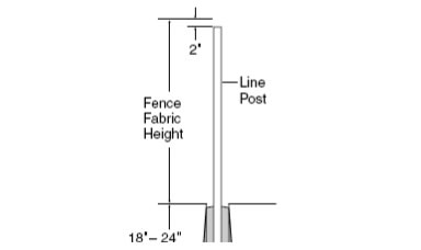
Line Posts: Fence posts spaced at regular intervals between terminal posts throughout each stretch
of fence.
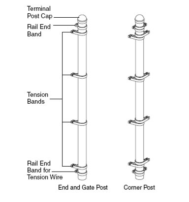
Terminal Posts: Fence posts that include end, gate, corner and straining posts.
End Posts: Fence posts positioned at the ends of a stretch of fence.
Heavy Duty Chainlink Gates
Gates: Defined as the distance between the inside faces of the gate posts.
Gate Posts: The two fence posts forming a gateway.
Corner Posts: Fence posts positioned at corners and changes or direction greater than ten
degrees.
Straining Posts: Fence posts positioned at changes in grade greater than thirty degrees.
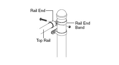
Top Rail: A tubular or fabricated steel section continuously joined by means of sleeves or couplings
throughout each stretch of fence extending between terminal posts.
Wire: Wire used for bracing terminal posts.
Top Wire: Wire installed at the top of the fence and extending throughout each stretch of fence between terminal posts.
Bottom Wire: Wire installed at the bottom of the fence and extending throughout each stretch of fence between terminal posts.
Fittings: Mechanical connections of various designs, shapes and metals to join fence components into an integral structure.
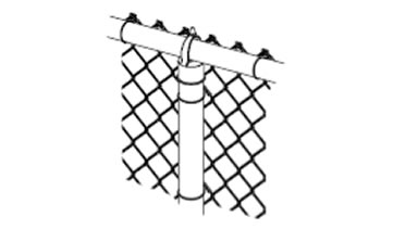
Wire Ties: Wire used to tie chain link fence fabric to line posts, bottom wires and top rails or top wires.
Chain Link Mesh
Mesh material: Electro galv. and hot dipped galvanized wire.
Mesh wire diameter: BWG8 to BWG14.
Opening:1"-3".
Mesh length:15-50m, width:1 - 3m
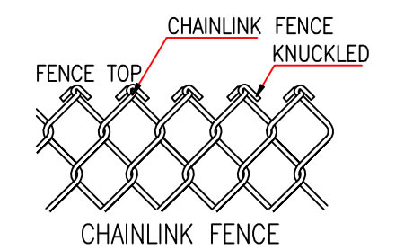
Fabric Top Style
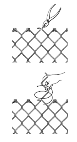
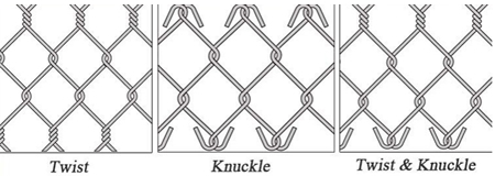
Knuckled: The type of selvage obtained by interlocking adjacent wire ends, in pairs, and then bending the wire ends back into a closed loop.
Barbed: The type of selvage obtained by interlocking adjacent wire ends, in pairs, and then twisting the wire at least two turns with the wire ends above the twist.
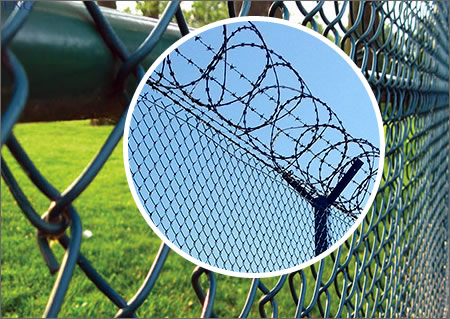
Barbed Wire: Twisted longitudinal wires, tensioned line wires, barbed or concertina razor barbed, attached to top rails.
Non Shrink Cement Grout: means a bedding compound that is inert and free from shrinkage.
Part List:
Security Fencing System Installation Instructions
The work performed in field fabrication and erection of Fencing systems.
This procedure applies to all work in connection with field fabrication of Fencing System. And smaller
subassemblies and erection of all chain link fencing systems including gates and barbed concertina.
Installation PDF References:
Determine the location of terminal post and position of fence gate
Setting Terminal and Line Posts
Securing Wire to Chain Link Fabric
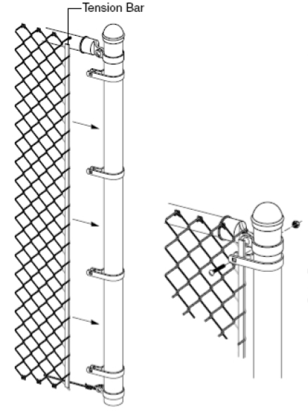
Attaching Fabrics to Posts and Rails and Removing Excess Fabrics
Adjusting Chain Link Fabric and Fastening with Tie Wire
Installation of Gate Applied to Both Single and Double Gate
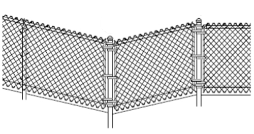
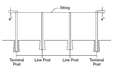
50 x 50 MM GALVANISED MESH SECURITY FENCING SYSTEM
Notes:
All wires confirm to BS 443 and PVC coated;
All metals are hot dip galvanized and pvc coated to 300 microns in green color (RAL-6005).
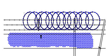
PDF references:
Panels with Posts and Tops
Elevation
Dropper Bar
Brace Details
Primary security line chain-link fence and barrier construction and upgrade
General
This section of the specification forms part of the Contract Documents. this section covers the chain-link fence and project barriers.
» Material Certification
Submit manufacturer's test data and certification al least 2 week prior to commencing work. Include stamped, signed, and dated manufacturer's drawings, information and shop drawing where pertinent.
» Security fence c/w perimeter barrier will be measured in metres. Our services include materials, installation, testing, grading, compacting and all work incidental to the completed Work. Supply and installation of the chain link mesh, all the posts, rails, braces, electrical grounds, barriers, tension wires and ties shall be incidental to the installation of the fence. Installation of the concertina razor wire shall also be incidental to the installation of the fence.
Products
» Materials
1, FABRIC
The fabric shall be woven with a 9-gauge galvanized steel wire in a 2-inch(50 mm) mesh and shall meet the requirements of ASTM A 392, Class 2.
2, Razor Wire
Concertina razor wire shall be 2 - strand 12-1/2 gauge zinc-coated wire with razor barbs wire and shall conform to the requirements of ASTM A 121, Class 3, Chain Link Fence Grade.
3, Posts, rails and braces
Line posts, rails, and braces shall conform to the requirements of ASTM F-1043 or ASTM F 1083 as follows:
(1) Galvanized tubular steel pipe shall conform to the requirements of Group IA, (Schedule 40) coatings conforming to Type A, or Group IC (High Strength Pipe) , External coating Type B, and internal coating Type B or D.
(2) Posts, rails, and braces furnished for use in conjunction with aluminum alloy fabric shall be aluminum alloy or composite.
(3) Posts, rails, and braces, with the exception of galvanized steel conforming to F 1043 or ASTM F 1083, Group 1A, or aluminum alloy, shall demonstrate the ability to withstand testing in salt spray in accordance with ASTM B 117as follows:
(a) External: 1,000 hours with a maximum of 5% red rust.
(b) Internal: 650 hours with a maximum of 5% red rust.
4, Wire Ties and Tension Wires
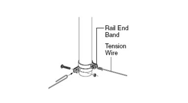
Wire ties for use in conjunction with a given type of fabric type. Top and bottom tension wire shall be 7-gauge marcelled steel wire with the same coating as the fabric type and shall conform to ASTM A 824.
5, Miscellaneous Fittings and Hardware
Miscellaneous steel fittings and hardware for use with zinc-coated steel fabric shall be of commercial grade steel or better quality, wrought or cast as appropriated to the article, and sufficient in strength to provide a balanced design when used in conjunction with fabric posts, and wires of the quality specified herein. All steel fittings and hardware shall be protected with a zinc coating applied in conformance with ASTM A153. Razor barbed wire support arms shall withstand a load of 250 pounds(113 kg) applied vertically to the outermost end of the arm.
6, Concrete
Concrete shall be of a commercial grade with a minimum 28-day compressive strength of 3,000 psi(17 240 kPa).
7, Marking
Each roll of fabric shall carry a tag showing the kind of base metal(steel, aluminum, or aluminum alloy number), kind of coating, the gauge of the wire, the length of fencing in the roll, and the name of the manufacturer. Posts, wire, and other fittings shall be identified as manufacturer, kind of base metal (steel, aluminum, or aluminum alloy number), and kind of coating.
8, Precast structural concrete:
To Section 03410 - Precast Concrete: except 28 day compression strength 35 Mpa.
9, Concrete reinforcement:
To Section 03200 - Concrete Reinforcement
Permissible dimensional tolerances of the barriers
» Cross-sectional dimensions shall not vary form design by more than 6mm. Vertical centerline shall not be out of plumb by more than 6 mm.
» Longitudinal dimensions shall not vary from design by more than 6 mm in 3 m of barrier section and not exceed 20 mm per section
» Location of anchoring is specified by supplier.
Submittals
» Manufacturer's Catalog Data
1, Chain-Link Fencing Components
2, Accessories
3, Gate Operator
» Certificates of Compliance
1, Fabric
2, Posts
3, Braces
4, Framing
5, Rails
6, Tension Wires
Execution
» CLEARING FENCE LINE. All trees, brush, stumps, logs, and other debris which would interfere with the proper construction of the fence in the required location shall be removed a minimum width of 500 mm on each side of the fence centerline before starting fencing operations.
» INSTALLING POSTS. All posts shall be set on the concrete barriers at the required dimension and depth and shall be spaced not more than 3m apart and should be set a minimum of 400 mm in the concrete barrier. The posts holes shall be in proper alignment so that there is a minimum of 75 mm of concrete on all sides of the posts. The posts may be welded to a galvanized plate to be bolted on the concete barrier. Alternate connection details will be revicwed by the Airport Authority before approving the installation.
The concrete shall have a smooth finish. All posts shall be set plumb and to the required grade and alignment. No Materials shall be installed on the posts, nor shall the posts be disturbed in any manner within 7 days after the individual post, footing is completed.
After the posts are set, the remainder of the drilled hole shall be filled with grout, composed of one part Portland cement and two parts mortar sand.
» INSTALLING BRACES. Horizontal brace rails, with diagonal truss rods and turnbuckles, shall be installed at all terminal posts or the fence alignment changes more than 30 degrees.
» INSTALLING FABRIC. The wire fabric shall be firmly attached to the posts and braced in the manner shown on the plans. All wire shall be streteched taut and shall be installed to the required elevations. The fence shall generally follow the contour of the tround, with the bottom of the fence fabric no less than 25 mm or more than 100 mm from the top of the concrete barrier. Grading shall be performed where necessary to provide a neat appearance.
» ELECTRICAL GROUNDS. Eletrical grounds shall be constructed where a power lin passes over the fence and at 500-foot(150 m) intervals. The ground shall be installed directly below the point of crossing of the power line. The ground shall be accomplished with a copper clad rod 3 metres long and a minimum of 20 mm in diameter driven vertically until the top is 150 mm below the ground surface. A No. 6 solid copper conductor shall be clamped to the rod and the fence in such a manner tha each element of the fence is grounded. Installation of ground rods shall not constitute a pay item and shall be considered incidental to fence construction.
Galvanized Wire Mesh Roll Specifications:
| Opening ( mm ) | Wire diameter ( mm ) | Width of the roll ( m ) | Length of the roll ( m ) |
| 60 mm | 2 mm | 2 m | 15 m |
| 70 mm | 2 mm | 2 m | 15 m |
| 60 mm | 2.6 mm | 1.5 m | 15 m |
| 70 mm | 2.6 mm | 1.5 m | 15 m |
| 60 mm | 2.6 mm | 2 m | 15 m |
| 70 mm | 2.6 mm | 2 m | 15 m |